Сores Nanocrystalline with high permeability

MSFN series

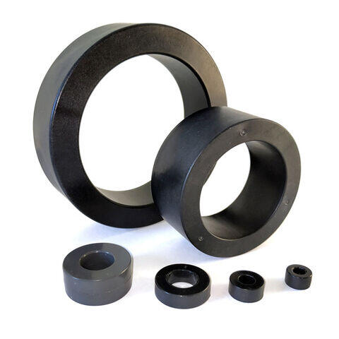
Magnetic cores of the MSFN series (KVSU.684459.093TU) are made of a thin (18 ± 2 μm) nanocrystalline ribbon AMAG 200C based on iron and are distinguished by high initial magnetic permeability in a wide frequency range, high saturation induction, increased operating temperature (up to +155 °C), good temperature stability. Cores are intended for use as a magnetic system of common-mode filter chokes, measuring current transformers, residual current devices, etc.

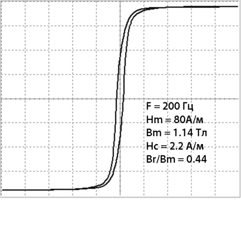
The MSFN series magnetic cores have a typical initial magnetic permeability of 100 000 (at a frequency of 50 Hz). At 10 kHz, the typical initial permeability is 85 000.

Common mode filter chokes based on the MSFN core require fewer winding turns, resulting in low parasitic capacitance and high resonant frequency. They are smaller and provide higher insertion loss over a wide frequency range than traditional ferrite and permalloy products. Due to the high noise suppression ratio, in most cases, it is possible to replace a two-stage common-mode filter based on ferrites with a single-stage filter based on the MSFN series core. The frequency range in the power mode is up to 1 MHz, in the signal mode up to 400 MHz.

Cores have a typical magnetic permeability of 90,000 (at a frequency of 10 kHz) or more. Common mode chokes based on the MSFN cores require fewer winding turns, resulting in low parasitic capacitance and high resonant frequency. They are smaller and provide higher insertion loss over a wide frequency range than traditional ferrite and permalloy products.


Typical Application: EMI Suppression Chokes

The MSFN series of cores is actively used in common mode chokes of the series DS2 и DS3.


Dimensions and basic characteristics

MSFNL-T series

Core name

Dimensions*

in container
(without container)
(D-d-H)
(mm)

Effective section
Seff,

(mm2)

Midline length
lmid,

(mm)

Weight in container, g
(without container, g) **
Inductance coefficient
AL ***, μH / turn2
(+40/-25%)
10 kHz
20
mA × turn
100 kHz
20
mA × turn


In aluminum container

MSFNL-07A-T

7,3 – 3,1 – 4,1
(7,0 – 3,5 – 3,8)
4,8 16,5 0,62
(0,58)
19,6 -
MSFNL-08S-T

8,8 – 3,2 – 4,0
(8,0 – 4,0 – 3,0)
4,3 18,8 0,67
(0,6)
15,3 -
  • * OD, HT, D, H – no more; ID, d – no less.

  • ** Deviation of the mass of magnetic cores (without container) no more than ± 10%.

  • *** The nominal value of the inductance of a single-turn winding.


MSFN-TH series

Core name

Dimensions*

in container
(without container)
(D-d-H)
(mm)

Effective section
Seff,

(mm2)

Midline length
lmid,

(mm)

Weight in container, g
(without container, g) **
Inductance coefficient
AL ***, μH / turn2
(+40/-25%)
10 kHz
20
mA × turn
100 kHz
20
mA × turn


In a plastic container

MSFN-10S-TH

11,4 – 5,0 – 6,1
(10,0 – 6,7 – 4,5)
5,3 26,2 1,45
(1,0)
28,0 6,9
MSFN-12A-TH

14,2 – 6,4 – 6,5
(12,0 – 8,0 – 3,0)
4,3 31,4 1,6
(1,0)
16,0 4,6
MSFN-12S-TH

14,2 – 6,4 – 6,5
(12,0 – 8,0 – 4,5)
6,5 31,4 2,3
(1,5)
28,2 6,9
MSFN-15A-TH

16,9 – 10,0 – 6,5
(15,0 – 12,0 – 4,5)
4,9 42,4 2,3
(1,5)
15,7 3,8
MSFN-16A-TH

18,0 – 8,0 – 8,3
(16,0 – 10,0 – 6,0)
13,0 40,8 5,3
(3,9)
42,2 10,6
MSFN-18S-TH

20,0 – 10,2 – 6,6
(18,0 – 12,0 – 4,5)
9,7 47,1 4,6
(3,3)
27,7 6,9
MSFN-20A-TH

22,7 – 10,2 – 10,3
(20,0 – 12,5 – 8,0)
21,6 51,0 10,9
(8,0)
58,0 14,1
MSFN-25A-TH

27,9 – 17,1 – 12,9
(25,0 – 20,0 – 10,0)
18,0 70,7 14,1
(9,3)
27,0 8,5
MSFN-25B-TH1

27,0 – 13,1 – 5,8
(25,0 – 15,0 – 4,0)
14,4 62,8 8,7
(6,6)
16,5 9,0
MSFN-25D-TH1

27,6 – 13,4 – 10,6
(25,0 – 15,0 – 8,0)
28,8 62,8 13,2 34,6 15,3
MSFN-25S-TH

28,6 – 13,6 – 12,5
(25,0 – 16,0 – 10,0)
32,4 64,4 20,3
(15,2)
69,5 16,8
MSFN-30S-TH

33,0 – 17,6 – 12,9
(30,0 – 20,0 – 10,0)
36,0 78,5 26,8
(20,6)
57,6 15,3
MSFN-30S-TH1

32,7 – 17,5 – 5,4
(30,0 – 20,0 – 3,0)
10,8 78,5 10,2
(6,2)
11,0 6,2
MSFN-32S-TH

34,8 – 17,4 – 12,8
(32,0 – 20,0 – 10,0)
43,2 81,6 33,0
(25,7)
63,3 17,7
MSFN-40A-TH

42,7 – 28,8 – 18,2
(40,0 – 32,0 – 15,0)
43,2 113,0 48,6
(35,6)
50,4 12,8
MSFN-40S-TH

40,9 – 23,2 – 15,5
(38,0 – 26,0 – 12,0)
51,8 100,5 47,4
(38,0)
70,8 17,2
MSFN-45S-TH1

48,3 – 21,7 – 23,5
(45,0 – 25,0 – 20,0)
144,0 109,9 141
(115,5)
133,0 43,8
MSFN-48S-TH1

53,0 – 21,5 – 24,0
(48,0 – 25,0 – 20,0)
165,6 114,6 165
(138,6)
135 35
MSFN-50S-TH1

54,0 – 36,0 – 24,1
(50,0 – 40,0 – 20,0)
72,0 141,3 104,4
(74,3)
43,4 17,0
MSFN-60S-TH

64,5 – 40,5 – 25,0
(60,0 – 45,0 – 20,0)
108,0 164,9 166
(130)
63,0 21,8
MSFN-60A-TH

64,1 – 36,0 – 34,5
(60,0 – 40,0 – 30,0)
216,0 157,0 287
(247,6)
133,7 46,0
MSFN-63A-TH

67,5 – 46,5 – 28,8
(63,0 – 50,0 – 25,0)
117,0 177,4 194
(151,5)
58,1 22,0
MSFN-80A-TH

84,5 – 59,0 – 29,6
(80.0 – 63.0 – 25.0)
153,0 224,5 298
(250,8)
58,7 22,8
MSFN-100S-TH

105,0 – 75,3 – 25,0
(100,0 – 80,0 – 20,0)
144,0 282,6 356
(297,1)
47,5 17,0


Paint coating

MSFNP-10S-TH

11,0 – 5,5 – 5,5
(10,0 – 6,7 – 4,5)
5,3 26,2 1,34
(1,0)
22,4 5,5
MSFNP-12A-TH

13,0 – 7,0 – 4,0
(12,0 – 8,0 - 3,0)
4,3 31,4 1,32
(1,0)
12,8 3,6
MSFNP-12S-TH

13,0 – 7,0 – 5,5
(12,0 – 8,0 – 4,5)
6,5 31,4 1,90
(1,5)
22,5 5,5
MSFNP-15A-TH

16,0 – 11,0 – 5,5
(15,0 – 12,0 – 4,5)
4,9 42,4 2,00
(1,5)
12,5 3,0
MSFNP-16A-TH

17,0 – 9,0 – 7,0
(16,0 – 10,0 – 6,0)
13,0 40,8 4,59
(3,9)
33,7 8,4
MSFNP-18S-TH

19,0 – 11,0 – 5,5
(18,0 – 12,0 – 4,5)
9,7 47,1 3,98
(3,3)
22,1 5,5
MSFNP-20A-TH

21,0 – 11,5 – 9,0
(20,0 – 12,5 – 8,0)
21,6 51,0 9,11
(8,0)
46,4 11,2
MSFNP-25A-TH

26,0 – 19,0 – 11,0
(25,0 – 20,0 – 10,0)
18,0 70,7 10,92
(9,3)
21,6 6,8
MSFNP-25S-TH

26,0 – 17,0 – 11,0
(25,0 – 16,0 – 10,0)
32,4 64,4 15,69
(15,2)
55,6 13,4
MSFNP-32S-TH

33,0 – 19,0 – 11,0
(32,0 – 20,0 – 10,0)
43,2 81,6 28,06
(25,7)
50,6 14,1
MSFNP-40A-TH

41,0 – 31,0 – 16,0
(40,0 – 32,0 – 15,0)
43,2 113,0 39,44
(35,6)
40,3 10,2
MSFNP-40S-TH

39,0 – 25,0 – 13,0
(38,0 – 26,0 – 12,0)
51,8 100,5 41,25
(38,0)
56,6 13,7
MSFNP-45S-TH

46,0 – 26,0 – 21,0
(45,0 – 25,0 – 20,0)
144,0 109,9 117,37
(115,5)
106 35,0
  • * OD, HT, D, H – no more; ID, d – no less.

  • ** The deviation of the mass of the magnetic cores (without the container) is not more than ± 10%.

  • *** The nominal value of the inductance of a single-turn winding.

Note:

  • It is allowed to supply cores of other standard sizes, including in containers supplied by the Customer under a separate agreement.


Program for calculating common-mode filter chokes

Specifications (extract) KVSU.684459.093 TU (MSFN series)

Application

  • Common Mode EMC Filters
  • High precision current transformers
  • Pulse transformers
  • RCDs (Safety Disconnect Devices)
  • Telecommunication systems

Advantages

  • High magnetic permeability
  • Reduces the size of filter chokes
  • Reduces the number of turns of the choke winding
  • Low resistance
  • Low losses in the cores
  • Low wire loss
  • High impedance choke over wide frequency ranges
  • High resonant frequency of the choke
  • Increased operating temperature and good temperature stability


Additional parameters and characteristics

Typical frequency dependence of permeability
Frequency dependence of impedance
(MSFN-20A-TH, one-turn winding)
Typical attenuation (single-phase two-winding choke)
Temperature dependence of permeability
Typical MSFN hysteresis loop

The main characteristics of the material used

  • Material AMAG 200C
  • Saturation induction, B10 (25°C) 1,16 T
  • Saturation induction, B10 (90°C) 1,10 T
  • Curie temperature, Tc 560 °C
  • Operating temperature range from –60°C to +155°C
  • Magnetostriction, less 0,5x10⁻⁶
  • Initial magnetic permeability (50 Hz) – 100 000 (+40/-25%)
  • Initial magnetic permeability (10 kHz) – 85 000 (+40/-25%)
  • Initial magnetic permeability (100 kHz) – 26 500 (+40/-25%)

Design

The MSFN-TH series is available in two designs:

  • 1. Flame retardant plastic container (MSFN-TH). A plastic container with a rigid structure and rounded edges provides reliable mechanical protection of the magnetic circuit from external influences while maintaining its properties, as well as the ability to apply winding with a wire of large diameter.
  • 2. Powder coated with epoxy paint (MSFNP-TH). The dimensions of the magnetic circuit are reduced, but the parameters deteriorate due to additional impregnation and mechanical action on the material of the magnetic circuit.

MSFNL-T series in production:

  • 3. In a thin walled aluminum alloy container (MSFNL-T). The dimensions of the magnetic circuit are reduced, but the parameters deteriorate due to additional impregnation and mechanical impact on the material of the magnetic circuit.

Temperature range -60 °C to +155 °C.


Recording example  

MSFNP-10S-TH, where:

  • MS – MSTATOR;
  • F – purpose (Filters);
  • N – nanocrystalline alloy;
  • No index – plastic container;
  • P – paint coating;
  • L – aluminum container;
  • 10 – outer diameter, mm;
  • A, S – sectional designation;
  • T – heat treatment in a transverse magnetic field;
  • TH – precision annealing in a strong transverse magnetic field
  • TH1 – the container has protrusions for installing a dielectric partition